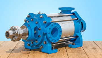
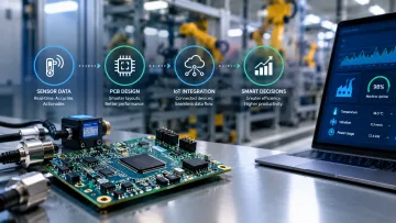
Ten years ago, the amp reading on a pump motor was something a technician glanced at during startup and forgot by lunchtime. The useful numbers were supposed to come from the suction gauge, the discharge gauge, the vibration probe bolted to the bearing housing, and, if the budget allowed, a flow meter in the discharge line. Current draw sat on a panel meter nobody logged. Today, the opposite is true.
The motor current is sampled constantly by the drive, trended against baseline, and read as a diagnostic channel in its own right. The reason that matters is simple: every other sensor on the skid costs money to install, calibrate, and maintain. The current signal is already there, for free, the moment the motor is energized.
Operators who have figured this out are catching cavitation, clogged strainers, worn impellers, and dry-running conditions days or weeks before the equipment that was supposed to catch those failures ever flags them.
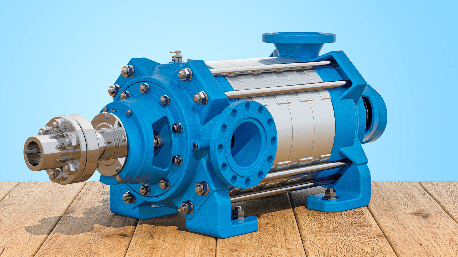
Why is amp draw suddenly treated as a sensor?
The hardware caught up. A modern variable frequency drive samples motor current thousands of times per second and already does the math a dedicated analyzer used to charge for. That turned the drive into a diagnostic instrument that happens to also spin the motor. Danfoss and other OEMs now market cavitation detection built directly into the drive, using current signature analysis to pick up the turbulence signature without a single added transducer.
The economics did the rest. A vibration sensor, its cabling, its gateway, and the analytics subscription behind it can run into the thousands per point. The motor current channel is a line item the drive already exposes over Modbus or Ethernet/IP. For a plant with hundreds of pumps, avoiding that per-point hardware cost on every skid is the reason this approach spread.
What can the current signal actually tell you?
More than most engineers assume. Current draw tracks hydraulic load in a predictable way, so anything that changes the load changes the amps. The relationship between shaft power, flow, and head on the pump curve is laid out clearly in this centrifugal pump power guide, and it is the foundation for reading the current signal correctly. The art is knowing which pattern maps to which failure. None of this requires a new instrument on the skid. It requires reading what the motor is already telling you.
How do you set a baseline that’s worth trending against?
A current trend is only useful if you know what good looks like. That means capturing the pump’s amp draw at known operating points when the equipment is clean, new, and running at its intended duty. The sizing calculation that produced the motor in the first place is the right starting document, because it ties shaft power to flow and head on the actual curve.
Set two bands, not one. A tight band flags drift. A wider band flags events. The tight band is where you catch an impeller losing a few percent of efficiency over a quarter. The wider band is where you catch a strainer that fouled overnight. Running one without the other either buries you in nuisance alarms or misses the slow failures entirely.
Does this replace vibration monitoring?
No, and anyone selling it as a replacement is overselling. Vibration still wins on bearing-specific diagnosis, on gear mesh, and on anything downstream of the coupling where the current signal has already been filtered by the motor’s own dynamics. What amp draw changes is the triage order.
Current trending can serve as the usually-on screen. Vibration becomes the deeper look you reach for once the current data says something is off. On a plant with hundreds of pumps and a handful of analysts, that ordering is the difference between a reactive maintenance program and a predictive one. The expensive sensors go on the pumps the cheap sensor flagged.
Where does this fail if you’re not careful?
The current signal is a load signal. Anything that changes the load unrelated to the pump’s health will move the amps, and if you don’t account for that, you’ll chase ghosts.
Suction tank level, fluid viscosity shifts with temperature, parallel pumps cycling on and off, a control valve throttling downstream, a VFD ramping between speeds, all of these move amps for reasons that have nothing to do with impeller wear.
The fix is context. Pair the current trend with the handful of signals that explain it: speed command from the drive, discharge pressure, and tank level where it matters. With those three alongside the amps, the diagnostic becomes trustworthy.
Without them, the amp alarm is noise with a timestamp. Pumps are a major end-use of motor energy in industrial plants, so the payoff for getting this reading right is real, both in avoided downtime and in energy the plant stops wasting on degraded equipment.