PWM waveform is commonly used in many electronic devices that are around us. Let’s find out what you need to know about how to generate the PWM waveform by using hardware and software tools!
What is PWM and how does it work?
PWM (Pulse Width Modulation) is a type of electrical signal which looks like a kind of a square wave at first glance. In this case, the arbitrary periodic value is computed exactly as for the regular square wave, although instead of using calculus, it is enough to use simple calculations on numbers only. The arbitrary periodic value of the PWM waveform is determined by the so-called duty cycle, i.e. the duration of the high state in relation to the duration of a whole single time period. Effect of duty cycle on the arbitrary periodic value of the signal presents the Fig. 1.
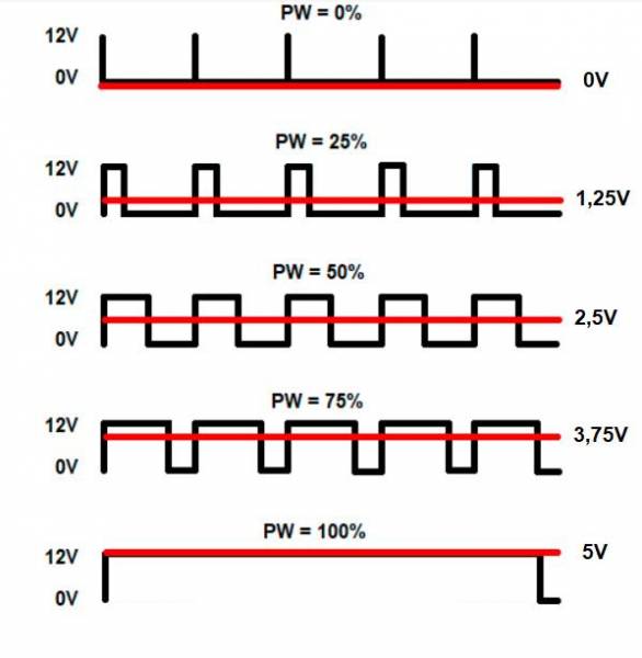
The oscillograms in this figure show that the higher the duty cycle (pulse width) value, the higher the PWM waveform average value. The PWM method was invented in the middle of the 70s of the 20th century. The most popular PWM applications are lighting and motor control systems, test and measurement instruments, as well as music synthesizers. The PWM waveform can be generated using both hardware and software.
Generating PWM waveform by using 555 timer IC
The LM555 is one of the most popular integrated circuits that has been remembered in the history of electronics as “The IC time machine”. It is a kind of bridge between analog and digital electronics. By combining its pinouts appropriately, it can be configured as a monostable singular pulse generator, reset-set bi-stable flip-flop, and also as a periodical square wave generator (astable) w / fixed or variable frequency. The fig. 2 presents schematic of 555 timer IC in an astable generator configuration. The supply voltage is 6.4V, so the high level on pinout no. 3 is close to 5V (TTL logic level high). By varying position of RV1 potentiometer we changing the duty cycle of the output signal. Frequency of the output waveform depending on the values of R1 and R2 resistors and C1 capacitor. Additionally, the circuit on the fig. 2 is modified to get fixed as possible frequency on the output. For 50% duty cycle, you have to use the same values of R1 and R2 resistors. The duty cycle adjustment range is from 50% to 90%. The higher the duty cycle value, the brighter the LED D3 lights up.

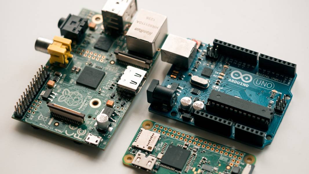
Generating PWM waveform by using Arduino board
PWM waveform can be also generated by using Arduino UNO R3 board. For this purpose, you have to use one of the I/O’s in the “DIGITAL (PWM)” section with “~” mark, for example pin no. 5. to which you have to connect the LED’s anode. Then you have to connect the LED’s cathode to the GND via 220R resistor. We will use a 10k potentiometer for the pulse width control. Connect the potentiometer as follows:
1 – GND
2 – A0 (ANALOG IN section)
3 – 5V
Then verify and upload the source code to the board:
//LED dimmer via PWM
int led_out = 5;
void setup() {
pinMode(led_out, OUTPUT);
}
void loop() {
for(int i=0; i<255; i++){
analogWrite(led_out, i);
delay(10);
}
for(int i=255; i>0; i–){
analogWrite(led_out, i);
delay(10);
}
}
The default PWM output frequency of Arduino is 490Hz, but by adding some another code lines you can change it too. Unlike the 555 timer IC, the Arduino can generate a PWM waveform with duty cycle 1% – 99%, but it takes little much more space than IC with few additional resistors and capacitors. If You would like to purchase the 555 timer IC or Arduino kits and modules, visit the Botland Store – the official vendor of Arduino boards.
Founder Dinis Guarda
IntelligentHQ Your New Business Network.
IntelligentHQ is a Business network and an expert source for finance, capital markets and intelligence for thousands of global business professionals, startups, and companies.
We exist at the point of intersection between technology, social media, finance and innovation.
IntelligentHQ leverages innovation and scale of social digital technology, analytics, news, and distribution to create an unparalleled, full digital medium and social business networks spectrum.
IntelligentHQ is working hard, to become a trusted, and indispensable source of business news and analytics, within financial services and its associated supply chains and ecosystems